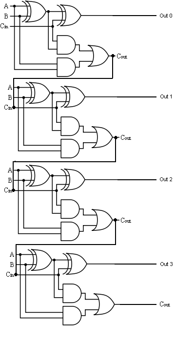
4 Bit Adder Schematic Diagram 4-bit Adder And Subtractor Cir
4 bit adder circuit diagram » schema digital Let's learn computing: 4 bit adder/subtractor circuit Download 4 bit adder circuit stick and logic diagram
boolean algebra - 2 bit adder implementation - Mathematics Stack Exchange
Download 4 bit adder circuit stick and logic diagram Design a full adder and subtractor circuit 4 bit adder schematic
Combinational and sequential design of a 4-bit adder. (a) ha circuit
Full-adder circuit, the schematic diagram and how it works – deeptronicFull adder circuit – how it works Add a circuit diagramMake adder subtractor bit carry verilog binary using ripple 4bit want subtraction addition operation output hdl has value which.
4-bit adder subtractor4 bit adder schematic 😊 four bit parallel adder. 4 bit binary adder circuit / block diagram4 bit binary incrementer.

16a 4-bit binary adder/subtractor
8 bit parallel adder circuit diagram4 bit adder circuit diagram 4 bit adder schematic wiring totalBit binary bits output geeksforgeeks incremented.
2 bit adder circuit diagram4 bit adder diagram Adder bit parallel four circuit binary diagram subtractor logic digital full block example geeksforgeeks detailed discussion4 bit adder circuit diagram.

Fulll adder circuit diagram
4 bit binary adder circuit diagramAdder circuit diagram schematic bit full works figure 🎉 4 bit parallel adder theory. 5.9: four. 2022-10-30Adder logic.
Boolean algebra1 bit full adder circuit 1 bit adder schematic8-bit adder circuit diagram.

4-bit adder and subtractor circuit explained
Electrical – designing a 4-bit adder-subtractor circuit – valuable tech4-bit binary adder-subtractor Adder bit subtractor circuit carry ripple diagram logic using project build only computing learn let its digital indie electronicsBinary adder and subtractor circuits: half and full adder, subtractor.
8 bit adder circuitAdder logic .


4-bit Adder and Subtractor Circuit Explained - YouTube

4-bit Adder Subtractor - VLSI Verify

Full Adder Circuit – How it Works

Download 4 bit adder circuit stick and logic diagram - Educative Site

8-bit Adder Circuit Diagram

boolean algebra - 2 bit adder implementation - Mathematics Stack Exchange

Full-Adder Circuit, The Schematic Diagram and How It Works – Deeptronic
Fulll Adder Circuit Diagram